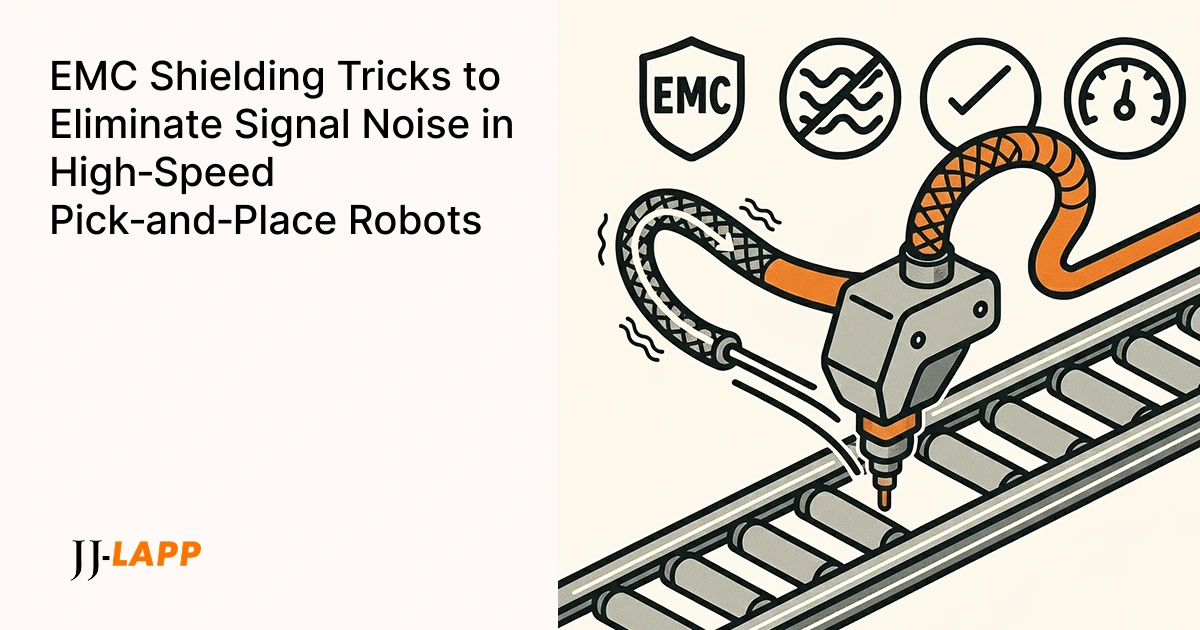
EMC Shielding for Smart Production Lines: A 4-Step Guide to Eliminating Signal Noise
Your new pick-and-place robot in Malaysia is quick, yet it keeps dropping parts. The gripper, PLC logic, and vision system are all fine. The hidden culprit? A Variable Frequency Drive (VFD) on the main conveyor spraying electrical noise that’s coupling into the gripper sensor via a poorly grounded shielded cable.
In a high-speed automated cell, electrical noise from motors and drives is inevitable. This “invisible” interference corrupts low-voltage signals and industrial Ethernet, causing intermittent faults that wreck uptime. Effective EMC (Electromagnetic Compatibility) isn’t just about choosing the right cable; it’s about designing a complete system. Here’s a practical, four-step method that stops noise at its source and gives your signals a clean ride.
Why EMI Matters: The Hidden Costs on Your Production Line
Intermittent, hard-to-diagnose faults caused by robotic arm EMI have tangible business costs:
- Availability: Every “ghost error” forces a line stoppage. These untraceable faults waste hours of engineering time and shred your OEE (Overall Equipment Effectiveness).
- Performance: Signal noise can force data retries or cause mechanical hesitations, directly impacting cycle time and throughput.
- Quality: Corrupted vision or sensor data leads to bad picks, inconsistent welds, and costly rework or scrap.
Understanding EMI in a Robotic Cell: The Invisible Threat
Variable-frequency drive (VFDs), servo drives, and switch-mode power supplies behave like small radio transmitters. They inject high-frequency noise into cabling (conducted interference) and radiate electromagnetic fields through space (radiated interference). While the drive itself may tolerate this noise, your sensitive encoders, sensors, and Ethernet communications do not.
The cure is a low-impedance, continuous path to ground for shield currents, combined with good physical separation. For system-level rules, the PROFINET Cabling & Interconnection Guideline is an essential resource on proper shielding and routing.
EMC Shielding Best Practices: Dos and Don’ts
For quick reference, here are the core principles for achieving robust EMC performance in any robotics application
| Best Practice (Low Impedance Path) | Common Mistake (High Impedance Path) | Why It Matters |
| Use cables with both braid and foil shields. | Using unshielded or foil-only cables for motion. | Provides broadband noise protection and mechanical durability against VFD interference. |
| Terminate shields with 360° EMC glands or connectors. | Improper or incomplete shield termination. | An ungrounded shield is ineffective; a poor connection can act as an antenna, worsening noise issues. |
| Separate power and signal cables in trays. | Running high-voltage power and Ethernet cables in parallel. | Prevents high-power noise from coupling into sensitive low-voltage signals. |
Your 4-Step Method for Robust EMC Shielding
Step 1: Select Cables with Braid & Foil for Full-Spectrum Shielding
Foil screens provide near-100% coverage and are excellent for blocking high-frequency noise. Tinned copper braids provide a low-resistance path for noise to drain to ground and offer better mechanical endurance. The best robotic cables combine both for broad-band protection. Aim for high braid coverage (>85%) and a robust PUR sheath for longevity.
Recommended LAPP Cables:
- ÖLFLEX® SERVO FD 796 CP (for servo/motor power)
- ETHERLINE® TORSION Cat.7 (for data in torsion applications)
Step 2: Ensure a Solid, 360° Shield Connection to Ground
A shielded cable without a proper ground connection is no better than an unshielded one. For a shield to be effective, it must be bonded to the ground point over a large surface area (360°). This creates a low-impedance path for electrical noise to be safely dissipated, preventing it from interfering with the signal conductors inside.
Step 3: Use EMC Glands for Fast, Reliable 360° Termination
A proper EMC cable gland makes a low-impedance, 360° bond repeatable and reliable. The SKINTOP® MS-M BRUSH clamps directly onto the shield with thousands of conductive spring-brush elements, ensuring fast, full-circumference contact as the cable enters a cabinet. This provides a neat, low-resistance connection that also includes strain relief.
Browse: EMC Cable Glands in the LAPP eShop.
Step 4: Route ‘Noisy’ and ‘Quiet’ Cables Separately
Physical separation is one of the simplest and most effective EMC strategies. Keep high-voltage power cables (noisy) physically separate from encoder, sensor, and Ethernet cables (quiet). Maintain a clear distance for parallel runs and cross cables at 90° if their paths must intersect.
Building a Complete EMC Shielding System with LAPP
- The Cable: Shielded, PUR-sheathed, robot-ready lines like ÖLFLEX® SERVO FD 796 CP and ETHERLINE® TORSION.
- The Gland: SKINTOP® MS-M BRUSH for fast, reliable 360° bonding at cabinet entries.
- The Connector: EPIC® metal-housed circular connectors maintain shield continuity through to the device.
Need help mapping the entire signal path? Contact LAPP for a quick EMC review.
EMC Shielding: Frequently Asked Questions (FAQ)
What is a ground loop? A ground loop can occur when different ground points are at different voltage potentials, causing unwanted current to flow in the shield. The best practice for high-frequency immunity in automation is to ensure a solid equipotential bonding system throughout your facility.
Is foil useful, or should I always pick a braided shield? Both are critical. Foil screens excel at blocking very high frequencies, while braids provide a low-resistance path to ground and are better against lower frequencies. High-performance robotic cables use both for full-band shielding.
The Bottom Line: Stop Hunting for ‘Ghost’ Errors
EMI-driven faults torch productivity. By implementing a system approach—a high-quality shielded cable with both braid and foil, 360° terminations via EMC glands, and disciplined routing—your robot signals will stay clean, and your line will run at peak performance.
Contact us today


